
English 
T: +86-571-8663-6649
E: hzbjys@hzbjys.com
E: hzbjys@hzbjys.com
7/F, 1st Building Of ZhongHao WangJiang International Center, NO.332 East WangJiang Road, HangZhou, ZheJiang, China.
Views: 0 Author: Site Editor Publish Time: 2026-11-06 Origin: Site


Copper holds a unique position across electrical, mechanical, and structural engineering. The metal combines unmatched electrical conductivity and rapid thermal dissipation with distinct mechanical constraints that separate it from carbon steel, stainless steel, and structural aluminum. Engineering teams face ongoing friction when specifying copper alloys and selecting fabrication methods. Choosing the wrong alloy temper causes sudden cracking along tight brake bends. Selecting an incompatible joining technique causes excessive heat spread, annealing surrounding zones and destroying dimensional tolerances. You need clear technical rules to balance mechanical strength, formability, and conductivity across your production runs. This guide details practical shop-floor procedures, alloy characteristics, machine parameters, and processing methods for custom copper manufacturing. We examine how to source raw material, choose cutting and bending setups, execute clean joins, and inspect completed parts to ensure your assemblies perform reliably under extreme service conditions.
Alloy Selection Matters: Differentiating between Oxygen-Free (OF) copper, electrolytic tough-pitch (ETP), and common alloys like brass or bronze based on end-use requirements.
Process Limitations: Understanding why copper’s ductility necessitates specific tooling considerations compared to ferrous metals.
Fabrication Trade-offs: The relationship between material thickness, heat-affected zones (HAZ) during welding, and dimensional stability.
Sourcing Strategy: How to align material specifications with project scale, waste management, and quality control.
Copper behaves differently than structural steels or standard aluminum alloys when subjected to mechanical forces. High-purity unalloyed copper exhibits a face-centered cubic crystal structure. This microscopic arrangement gives the metal exceptional ductility and thermal conductivity. However, it also promotes rapid work-hardening during forming operations. When evaluating materials for custom copper metalwork, engineers must identify the boundary where electrical efficiency balances against physical yield strength. Selecting an alloy strictly for its electrical rating can result in structural failure if the part experiences mechanical vibration or continuous dynamic loads.
Electrolytic Tough Pitch copper, designated as UNS C11000, serves as the standard commercial grade for electrical conductors, power distribution switchgear, and architectural sheet. C11000 contains an intentional oxygen concentration of 0.02% to 0.04%. These minute traces of oxygen gather harmful impurities like iron, sulfur, and arsenic at grain boundaries, precipitating them out into harmless oxides. This mechanism preserves high electrical conductivity, consistently reaching or exceeding 100% IACS. However, the presence of cuprous oxide creates severe vulnerability during thermal processing. When exposed to temperatures above 370 degrees Celsius in reducing atmospheres containing hydrogen, the hydrogen diffuses into the copper matrix. It reacts with cuprous oxide to form pressurized steam pockets along the grain boundaries. This phenomenon, known as hydrogen embrittlement, causes micro-fissuring and catastrophic mechanical failure under moderate physical stress.
To eliminate embrittlement risks, high-temperature manufacturing environments require Oxygen-Free Electronic copper, UNS C10100, or Oxygen-Free copper, UNS C10200. Refined through induction melting under protective gas covers, C10100 holds oxygen levels below 0.0005% while maintaining electrical conductivity at 101% IACS. It accommodates extensive brazing, automated orbital welding, and vacuum sealing operations without joint degradation. For mechanical assemblies where raw electrical performance takes a secondary role, phosphorus-deoxidized copper grades like UNS C12200 introduce 0.015% to 0.040% phosphorus. Phosphorus cleanses the melt of oxygen while retaining high ductility and corrosion resistance. This alloy serves as the primary feedstock for industrial heat exchanger tubing, architectural panels, and closed-loop refrigeration piping networks.
Defining functional success requires matching sheet gauge and temper to operating loads. Copper temper reflects the percentage of cold reduction applied to the stock following final mill annealing:
Dead Soft (O60 Temper): Fully recrystallized through thermal soaking. The material exhibits low yield strength, often around 69 to 75 MPa, but elongation frequently exceeds 40%. It accepts severe deformation, deep drawing, and acute edge hemlines without micro-fissuring.
Half-Hard (H02 Temper): Cold-rolled to approximately 21% reduction in cross-sectional area. Yield strength climbs to 250-290 MPa, cutting elongation down to 12-18%. It provides enough stiffness to resist sagging across wide spans while allowing standard 90-degree press brake bends over matching punch radii.
Hard (H04 Temper): Cold-worked to a 37% area reduction. Yield strength surpasses 330 MPa, while elongation drops below 6%. The metal holds strict flatness across punched faces but fractures quickly if bent across small radii without pre-annealing the bend line.
Spring Temper (H08 Temper): Heavily rolled with over 60% cold reduction. This creates an internal grain structure geared for contact springs and electrical clips that require high fatigue endurance without permanent plastic deformation.
Ignoring grain direction during forming leads to premature failure. Cold rolling elongates grains parallel to the rolling direction. Bending a hardened copper sheet parallel to these elongated grains concentrates tensile stress along single boundary rows, initiating microscopic edge cracks. Fabricators must orient critical bend lines perpendicular to the rolling direction. When parts demand multi-directional bends, specifying a half-hard or quarter-hard temper provides the ductility needed to avoid edge fracture along longitudinal and transverse axes.
Industrial power distribution platforms rely on pure copper to maintain continuous electrical service without excessive resistive heating. Massive low-voltage switchboards, high-voltage disconnect stations, and industrial transformer links require heavy-gauge copper busbars engineered with strict cross-sectional area targets. Engineers calculate cross-sections to limit thermal rise beneath 30 degrees Celsius above ambient under continuous rated currents. Oxygen-free C10100 plates are frequently chosen for high-vacuum circuit breakers, where outgassing cannot be tolerated. In alternating current distribution systems operating above several hundred amperes, alternating magnetic fields force electrons outward toward the conductor perimeter. Fabricators accommodate this skin effect by configuring high-amperage conductors out of wide, thin rectangular bars or hollow tubular busbars rather than heavy solid cylinders, minimizing overall material weight while maintaining cross-sectional conductance.
Thermal management hardware represents another widespread application for fabricated copper parts. Copper provides a thermal conductivity rating of roughly 390 Watts per meter-Kelvin at room temperature, outperforming structural 6061-T6 aluminum by nearly a two-to-one ratio. Modern data centers and high-density power converters generate localized heat fluxes exceeding 100 Watts per square centimeter. Managing these thermal densities requires liquid-cooled cold plates machined from dense flat copper plates. Coolant passages are machined directly into the plate faces via CNC milling or electrical discharge machining, followed by vacuum brazing of a cover plate to form hermetic, leak-proof internal channels. In industrial HVAC condensers and power plant heat recovery systems, expanded copper fin sheets are mechanical-press crimped over cold-drawn copper tubes to maximize contact surface area, maintaining thermal exchange rates in humid or chemically aggressive atmospheres.
Architectural installations leverage copper for long-term exterior durability. The natural oxidation sequence of exterior copper transforms the metal over several years. It transitions from a bright reflective mill finish into an intermediate dull brown cuprous oxide film, ultimately converting into a dense, basic copper sulfate and carbonate patina. This surface crust seals the underlying base metal away from moisture, oxygen, and industrial sulfur, delivering field lifespans exceeding a century without synthetic paints or barrier coatings. Architectural standing-seam roofs, decorative column enclosures, and perimeter rainwater systems require specific attention to thermal expansion. Copper exhibits a linear thermal expansion coefficient of approximately 16.5 micrometers per meter per degree Celsius. Long fascia panels and roof trays require floating, sliding attachment clips rather than rigid through-fasteners. Without sliding cleats, seasonal thermal expansion produces visible oil-canning waves and buckles thin-gauge architectural sheets.
Executing accurate copper sheet metal fabrication demands equipment configured for high thermal conductivity, low shear stiffness, and a strong tendency to gall against hardened tool steel. Standard production parameters developed for mild steel will cause rapid tooling wear, dimensional shift, and unacceptable edge roll when applied to raw copper stock.
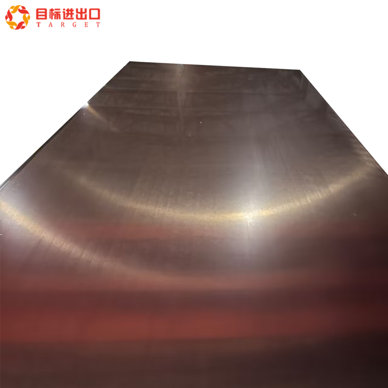
Separating copper plates into net-shape blanks requires careful selection between thermal beam energy and mechanical shearing. Industrial laser cutters historically struggled when cutting copper due to the metal's high optical reflectivity in the infrared spectrum. Standard carbon dioxide lasers emit beam wavelengths around 10.6 micrometers. Clean copper surfaces reflect over 95% of this beam energy straight back into the cutting head, damaging protective optics and resonator cavities. The industry transition to solid-state fiber lasers operating at 1.07-micrometer wavelengths resolved this hazard. Copper absorbs fiber laser energy much more readily, allowing stable cutting when paired with high-pressure oxygen or nitrogen assist gases.
Oxygen assist gas relies on an exothermic oxidation reaction to sever the metal, boosting travel speeds on plate thicknesses exceeding 4 millimeters. However, oxygen leaves a dark cupric oxide edge film that requires mechanical deburring or pickling baths before secondary welding. High-pressure nitrogen assist gas operates at pressures up to 18 bar, cleanly blowing molten metal out of the cut kerf without chemical reaction. Nitrogen cutting produces bright, oxide-free edges ready for immediate joining, though it requires substantial laser wattage to cut thicker plates.
Abrasive waterjet cutting serves as the standard process when thermal distortion must be avoided entirely. Operating at water pressures between 3,800 and 6,200 bar with fine mesh garnet abrasive, the cold-cutting stream induces zero thermal stress, eliminating heat-affected zones across flat copper sheet for fabrication. Waterjet cutting prevents thermal micro-cracking and material softening, making it the preferred method for cutting pre-hardened busbars or intricate gasket faces that require structural flatness within 0.1 millimeters across large dimensions.
Mechanical shearing provides the fastest separation speeds for straight rectangular cuts, but it introduces distinct mechanical edge challenges. Copper's high ductility allows the sheet to deform plasticly under the shear blade before the ultimate shear fracture occurs. This plastic deformation produces a rounded rollover zone on the top surface, an elongated burnish band, and a sharp tear-burr on the bottom edge. Fabricators must maintain razor-sharp high-carbon, high-chromium tool steel shear blades (such as D2 or A2) and dial in blade clearances precisely. Shear blade clearances for copper are kept between 3% and 5% of sheet thickness, noticeably tighter than the 7% to 10% clearances used for structural carbon steels. Excessive clearance pulls the soft copper down into the shear bed gap, generating deep edge burrs that tear tooling during subsequent press brake passes.
Press brake forming of copper demands strict adherence to minimum bend radii based on sheet hardness. When bending high-ductility, annealed (O60) copper, an inside bend radius equal to 0.5 times the material thickness prevents surface cracking. Moving to half-hard (H02) or fully hard (H04) tempers requires increasing the inside punch radius to 1.5 to 2.5 times the material thickness. Attempting an acute, knife-edge bend on hard copper tears the outer surface fibers, creating visible micro-cracks that degrade mechanical strength and drop local electrical cross-section by up to 25%.
Spring-back behavior in copper presents an interesting forming profile. In dead-soft condition, copper exhibits almost zero spring-back, remaining firmly where the punch stroke places it. Cold-worked tempers, however, retain significant internal elastic strain. Air-bending hard copper can result in 2 to 5 degrees of elastic spring-back after the ram unloads. Press brake technicians compensate for this spring-back through three primary shop techniques:
Over-Bending: Programming the CNC press brake backgauge and ram depth to over-stroke the bend angle by the calculated spring-back value, allowing the flange to rest naturally at the specified angle.
Bottom Bending: Forcing the punch deeper into the die opening so the metal enters full plastic deformation across its entire thickness, reducing internal residual elastic stresses.
Rotary Bending Tooling: Utilizing rotating cylindrical rocker dies that clamp the sheet securely while wiping the flange upward, which prevents surface scratching and lowers localized grain-boundary stress concentrations.
Plate rolling transforms flat sheets into cylindrical motor shells, condenser tubes, and architectural sleeves. Because copper stretches readily under lateral roll pressure, rolling operators must take light, progressive passes across dynamic three-roll or four-roll machines. Aggressive reduction passes thin the sheet non-uniformly, creating an hour-glass cross-section where the edges stretch wider than the supported center. Lubrication is mandatory throughout rolling operations; unlubricated copper easily galls and cold-welds to steel roll surfaces, transferring steel gouges back onto subsequent workpieces.
Punching and stamping require specialized die clearances. Soft copper tends to hug the punch face during withdrawal, causing high friction and tool wear. Punch tooling should incorporate a 1.5-degree back-taper relief above the cutting land, and strip strippers must provide substantial clamping force to prevent the sheet from pulling upward off the die. Applying high-pressure chlorinated or synthetic drawing oils prevents micro-welding between the copper sheet and the carbide punch face.
Joining copper components requires adjusting thermal parameters to match the metal's high thermal conductivity. Conventional arc welding heat concentrates locally in steel, melting the seam before surrounding metal can carry the thermal energy away. In contrast, copper conducts thermal energy away from the weld zone five times faster than carbon steel. Striking an arc on cold, unheated thick copper produces a cold lap, where the filler bead sits on top of the base metal without achieving metallurgical fusion.
Tungsten Inert Gas (TIG) and Metal Inert Gas (MIG) welding of copper require extensive preheating. For plates thicker than 3 millimeters, technicians preheat the entire component to 300 to 500 degrees Celsius using oxy-fuel torches or ceramic heating blankets before initiating the arc. This elevated background temperature lowers the thermal gradient, allowing the electric arc to maintain a stable, fluid puddle. Shielding gas composition is equally critical. While pure argon functions acceptably on thin-gauge sheets under 1.5 millimeters, welding thicker plates requires shielding gas mixtures containing 50% to 75% helium. Helium increases arc voltage and imparts a hotter, deeper thermal profile to the weld pool, achieving clean sidewall fusion without burning out the tungsten electrode.
Brazing serves as the primary joining process for structural copper assemblies, piping networks, and electrical bus manifolds. Brazing heats the assembly above 450 degrees Celsius but remains well below the copper melting point of 1,085 degrees Celsius. Capillary action draws molten filler metal into clearances between close-fitting mating surfaces. Common brazing alloys include copper-phosphorus (BCuP series) and silver-bearing formulations (BAg series). The phosphorus content in BCuP filler metals acts as a self-fluxing agent when joining copper to copper, actively stripping away atmospheric copper oxides during heating. This eliminates the need for secondary paste fluxes, avoiding trapped flux residues inside critical refrigeration or electrical fluid channels.
Precise electrical terminations require meticulous copper wire soldering to maintain joint conductivity and prevent premature fatigue failure. Soldering operates at temperatures below 450 degrees Celsius, using tin-lead or tin-silver-copper alloys. To ensure a sound mechanical and electrical bond, technicians strip the conductor insulation cleanly without nicking strands, apply a mild rosin-based flux to dissolve surface tarnish, and heat the joint directly with a regulated iron until the solder flows smoothly across all strand surfaces. Incomplete heating causes cold solder joints, characterized by high electrical resistance and poor mechanical strength.
High-volume part production shifts manufacturing away from flat sheets toward automated copper strip processing. Industrial stamping operations feed continuous copper strip directly from uncoiling reels through precision levelers, progressive multi-stage dies, and high-speed mechanical presses. This automated method cuts unit labor hours and reduces material scrap compared to loading individual blanks into manual machines.
Progressive stamping dies perform sequential cutting, piercing, coining, and bending across a single copper strip at speeds ranging from 60 to over 500 strokes per minute. Maintaining tight product tolerances requires continuous control over incoming raw material parameters. Coil camber—the lateral curvature deviation of the strip edge from a true straight line—must remain within 1 millimeter per meter of length. Excessive camber forces the strip off-center inside the die guides, breaking pilot pins and producing misaligned holes. Precision copper custom metal processing lines incorporate optical laser micrometers that measure coil thickness continuously, alerting operators if incoming strip gauge deviates outside mill specifications.
High-speed slitting lines divide wide master coils into narrow process strips. Slitting operations use opposing rotary circular knives mounted on parallel arbors. Maintaining tight knife clearance is critical to controlling strip burr. If rotary slitter knives wear down or arbor bearings develop axial runout, edge burrs increase significantly. In subsequent progressive forming passes or automated electrical winding stations, large slitting burrs slice through insulation tape and create inter-turn electrical shorts. High-precision slitters shave edge burrs down to less than 2% of metal thickness, often passing the cut strip through rotary edge-conditioning wheels to roll the slit edge into a safe, uniform round profile.
Surface finishing is the final stage of strip processing. Stamped components destined for electrical switchgear or battery interconnects frequently receive electroplated coatings to prevent tarnishing and maintain low contact resistance. Electroplated tin deposits provide a cost-effective, solderable corrosion barrier suitable for automotive fuse blocks and household breakers. For demanding industrial switchgear subject to repeated high-voltage arcing, electroplated silver deposits offer exceptional electrical conductivity and resist mechanical contact galling over tens of thousands of cycles.
Selecting the correct manufacturing path for copper parts requires a clear framework that balances production volume, component geometry, mechanical tolerances, and tooling lead times. Choosing the wrong production method leads to excessive material scrap and expensive secondary rework.
Fabrication Process | Dimensional Tolerance | Production Volume Fit | Setup / Tooling Effort | Primary Technical Limitation |
|---|---|---|---|---|
CNC Waterjet Cutting | +/- 0.08 mm | Prototypes to Low Volume | Minimal (CAD-to-machine) | Slow processing speed on thick stock; wet abrasive residue requires cleaning. |
Fiber Laser Cutting | +/- 0.05 mm | Low to Medium Volume | Minimal (CAD-to-machine) | Risk of thermal distortion on sheets under 1.0 mm; back-reflection risks on older heads. |
Progressive Die Stamping | +/- 0.02 mm | High to Ultra-High Volume | Very High (Complex hard tooling) | High initial tooling expense; design changes require expensive die modifications. |
Manual Press Brake Bending | +/- 0.40 mm | Prototypes to Small Batches | Low (Standard modular tooling) | Operator-dependent repeatability; potential surface tooling marks on soft copper. |
Four-Slide / Multislide Forming | +/- 0.03 mm | High Volume | High (Custom slide cams) | Restricted to strip widths under 75 mm and complex miniature geometries. |
Furnace Brazing | +/- 0.10 mm | Medium to High Volume | Moderate (Graphite/Inconel fixtures) | Entire part is fully annealed by furnace heat; loss of mechanical work-hardening. |
Production scale strongly dictates the transition point between cutting methods. For initial prototype runs and small batches up to 250 units, waterjet or fiber laser cutting paired with CNC press brakes offers the lowest development cost and fastest iteration speeds. These setups eliminate hard tooling, allowing engineers to refine hole patterns, flange lengths, and bend reliefs directly within CAD models. When production runs scale into tens of thousands of units, the material savings achieved by tight blank nesting inside progressive stamping dies, combined with sub-second cycle times, justify the initial investment in hard steel dies.
Managing operational scrap rates directly drives manufacturing efficiency. Copper carries a high raw material cost per kilogram compared to commercial aluminum or steel. High-efficiency nesting algorithms maximize blank yield across raw sheets, leaving narrow skeleton bridges between cut parts. Fabricators must maintain strict scrap collection procedures, segregating high-purity C11000 and C10100 offcuts away from leaded brass, silicon bronze, and standard shop steels. Clean, unmixed copper scrap commands a high resale value at recycling mills, recovering a significant portion of raw material costs.
Risk mitigation across precision copper processing requires systematic non-destructive testing and physical inspection protocols:
Eddy Current Conductivity Testing: Handheld conductivity meters verify that incoming copper lots meet the specified % IACS rating, confirming alloy purity before sheets enter the production queue.
Micro-Hardness Indentation: Vickers or Rockwell micro-hardness testing across bent flange cross-sections verifies that forming operations have not locally over-hardened or embrittled the grain matrix.
Dye Penetrant Inspection (DPI): Liquid penetrant testing highlights micro-fissures, porosity, and incomplete fusion along TIG and MIG weld beads before parts advance to sub-assembly.
Dimensional CMM Auditing: Automated Coordinate Measuring Machines map stamped or bent copper assemblies against 3D CAD step files to ensure mounting hole true-positions remain within tolerance after spring-back relaxation.
Manufacturing copper components requires compliance with internationally recognized industry standards. ASTM International establishes the core technical specifications governing copper material properties and test methods. ASTM B152 covers the standard requirements for copper sheet, strip, plate, and rolled bar across electrical and mechanical grades. It mandates chemical purity limits, tensile strength boundaries, and elongation minimums for every commercial temper. For applications involving precision electrical conductors, ASTM B187 governs copper busbars, shapes, and structural rods, defining electrical resistivity limits alongside mechanical hardness requirements.
Tubular products and thermal exchange components must align with ASTM B75 or ASTM B88, which control seamless copper tube manufacturing, burst pressures, wall-thickness tolerances, and internal cleanness standards. European engineering standards follow the DIN EN system. Grade EN CW004A designates standard electrolytic tough-pitch copper equivalent to C11000, while EN CW008A defines high-purity oxygen-free copper equivalent to C10200. Conformance to these metallurgical specifications guarantees that raw material sourced globally will exhibit consistent shear strength, ductility, and electrical performance inside automated production cells.
Environmental and safety compliance mandates adherence to RoHS (Restriction of Hazardous Substances) and REACH (Registration, Evaluation, Authorisation and Restriction of Chemicals) directives. Unalloyed copper is inherently free of restricted hazardous substances such as lead, cadmium, and hexavalent chromium. However, engineers must verify that post-machining passivation dips, protective bright-dip acid baths, and surface electroplating chemistries remain fully compliant with these environmental rules. In fire-safe architectural installations, copper achieves an absolute A1 non-combustible reaction-to-fire classification under ISO and national building codes, releasing zero toxic smoke or flaming droplets when exposed to structural blazes.
Successful copper manufacturing depends on matching the right alloy composition to functional thermal, electrical, and structural demands. You cannot approach copper using the same cutting clearances, bend setups, and heat inputs developed for steel. High thermal conductivity, optical reflectivity, and rapid work-hardening demand disciplined shop techniques. By systematically aligning alloy tempers, cutting technologies, and joining methods to your specific production volumes, you ensure your parts perform reliably in demanding service conditions.
Follow these actionable technical steps to initiate your next production run:
Review all engineering drawings to confirm that inside bend radii equal or exceed 1.5 times the material thickness on any parts using half-hard or hard copper stock.
Verify your required electrical conductivity threshold to determine whether economical C11000 tough-pitch copper meets the design criteria or if high-heat brazing demands C10100 oxygen-free material.
Audit prospective fabrication partners to verify they possess fiber lasers with back-reflection safeguards, precision waterjets, and helium-capable TIG welding setups.
Commission an initial prototype pilot batch of 10 to 50 units to evaluate spring-back, grain orientation, and hole clearances under actual production conditions before freezing final tooling designs.
A: Flat sheet fabrication involves handling individual, pre-cut rectangular pieces, making it ideal for low-volume, large, or custom parts. Strip processing utilizes continuous coils fed directly into automated stamping presses or roll formers. Strip processing significantly reduces material handling time and minimizes scrap in high-volume production runs.
A: Mitigating thermal warping requires strict heat management. Fabricators use heavy copper or aluminum backing bars to draw excess heat away from the weld zone. Utilizing pulsed TIG welding minimizes the overall heat input. Preheating the component uniformly reduces the temperature gradient, which prevents localized expansion and subsequent warping.
A: Temper dictates the metal's hardness and ductility. Soft, annealed tempers allow for deep drawing and tight-radius bending without cracking. Hard, cold-worked tempers provide necessary structural rigidity and mechanical strength but restrict the severity of forming operations. Selecting the correct temper balances formability with final part strength.
A: Oxygen-free copper lacks the microscopic oxygen inclusions found in standard electrolytic tough-pitch copper. These inclusions can cause hydrogen embrittlement when exposed to high heat. Removing impurities maximizes electron flow, providing the highest possible electrical conductivity and preventing structural failure in high-voltage or high-temperature environments.
A: Plasma cutting is preferred when processing very thick copper plates that exceed the maximum cutting capacity of available fiber lasers. While lasers provide superior precision on thin to medium gauges, plasma offers a faster, more cost-effective method for severing heavy structural copper, despite leaving a rougher edge.
A: Common defects include micro-cracking on bend lines, thermal distortion from welding, and surface oxidation. Avoid cracking by respecting minimum bend radii based on material temper. Prevent distortion by using waterjet cutting or managing weld heat input. Mitigate oxidation by applying immediate chemical passivation or mechanical finishing.
A: Copper raw material costs significantly more than steel. However, copper often requires less secondary finishing. It naturally resists corrosion, frequently eliminating the need for painting, powder coating, or galvanizing required by steel. This reduction in secondary processing can partially offset the higher initial material investment.


