
English 
T: +86-571-8663-6649
E: hzbjys@hzbjys.com
E: hzbjys@hzbjys.com
7/F, 1st Building Of ZhongHao WangJiang International Center, NO.332 East WangJiang Road, HangZhou, ZheJiang, China.
Views: 0 Author: Site Editor Publish Time: 2026-05-21 Origin: Site


Translating a CAD concept into a manufacturable aluminum shape often reveals a massive gap between theoretical engineering and factory floor reality. Overengineered profiles frequently lead to catastrophic die breakage, slow press speeds, and severely inflated per-foot production costs. A successful design process must systematically minimize tooling wear and eliminate unnecessary secondary machining steps. Engineers must also optimize the structural weight-to-strength ratio to keep material expenses in check. Failing to balance these factors results in wasted time, delayed launches, and blown manufacturing budgets.
This comprehensive guide provides structural engineers and procurement teams with evidence-based parameters to refine their initial drawings. You will discover practical ways to reduce lead times, optimize structural geometries, and evaluate potential manufacturing partners effectively. By following these proven guidelines, you can align your structural requirements with the physical realities of the extrusion process, ensuring a smooth transition from prototype to high-volume production.
Keep it within the "Sweet Spot": Limit the Circumscribing Circle Diameter (CCD) to under 8 inches and weight to under 3 lbs/ft for optimal cost-efficiency.
Uniformity is Critical: Maintain a maximum 2:1 ratio for adjacent wall thicknesses to prevent cooling distortion.
Avoid True Hollows Where Possible: Use 60-degree gaps in screw bosses and convert nested hollows to semi-hollows to drastically reduce die costs.
Plan for Post-Processing: Surface finishes like anodizing alter dimensional tolerances; index marks reduce downstream machining costs.
Before you finalize your CAD file, you must evaluate the baseline cost drivers of a custom Aluminum Extrusion Profile. Extrusion physics dictate how quickly and affordably a manufacturer can produce your part. Size and weight represent your primary mechanical constraints.
You should match your profile size to standard press capabilities. We measure profile size using the Circumscribing Circle Diameter (CCD). This is the smallest circle you can draw around the entire cross-section. Profiles fitting within a 1-inch to 10-inch CCD represent the industry standard. However, keeping the CCD under 8 inches drops production costs significantly. Smaller profiles fit on more common, widely available presses. If your design exceeds 10 inches, you restrict your options to a few specialized manufacturers, which drives up lead times.
Extrusion profitability and press speed rely heavily on material weight. You should target a weight-per-foot (Wt/Ft) between 0.100 and 3 lbs/ft. Heavier profiles force the machine operator to slow down the press. Slowing the press increases machine-hour costs. Heavy profiles also trap excess heat, complicating the cooling process and increasing raw material expenses. A lightweight, structurally optimized design runs faster and costs less.
Engineers must understand the relationship between total perimeter and cross-sectional area. This ratio defines the die difficulty factor. High-perimeter, low-area designs create massive friction inside the tool. This friction requires higher press pressures. Pushing metal through restricted spaces stresses the die and risks catastrophic tool failure.
Summary Chart: Core Extrusion Guidelines | |||
Parameter | Optimal Range | High-Cost Zone | Primary Impact |
|---|---|---|---|
Circumscribing Circle (CCD) | 1" to 8" | > 10" | Press availability and hourly rate |
Weight per Foot | 0.100 - 3.0 lbs/ft | > 5.0 lbs/ft | Extrusion speed and raw material cost |
Die Difficulty | Low Perimeter / High Area | High Perimeter / Low Area | Tooling lifespan and die breakage risk |
Micro-design choices determine whether your shape survives the press. You need strict risk mitigation guidelines to prevent die breakages and ensure dimensional stability across different aluminum profile types.
Maintain uniform wall thickness throughout your cross-section. If your design requires variations, you must keep the transition smooth. The thickness ratio of adjacent walls should never exceed 2:1. Abrupt changes cause the metal to cool unevenly. Uneven cooling leads to twisting, severe warping, or visible sink marks appearing on the opposite flat surface. These defects often trigger mass rejections during quality control.
Avoid deep, narrow channels at all costs. The "tongue ratio" measures the depth of a channel compared to its width. This ratio should not exceed 3:1. Higher ratios create a thin "die tongue" in the tool steel. The extreme pressure of flowing aluminum will easily snap this fragile steel tongue. For heatsink applications, you can stretch the fin length-to-thickness ratio, but keep it safely under 10:1.
Never leave corners sharp. Sharp internal corners create stress risers in the die steel, leading to premature cracking. Sharp external corners slow down metal flow and cause uneven surface finishes. You must specify a minimum corner radius of 0.015 inches (0.38mm) across your design. This simple change improves metal flow, reduces heat buildup, and extends die life.
Hollow shapes cost more money. True hollows require expensive bridge or porthole dies. These multi-part tools push the metal around a mandrel to create a closed void. You can drastically reduce costs by converting nested hollows into semi-hollows. Just introduce a small gap to open the shape.
Screw Bosses: Leave a 60-degree opening rather than designing a fully closed circle. This avoids the need for a Torpedo die.
Nested Cavities: If you have a tube inside a tube, break the outer wall slightly. This converts a difficult porthole design into a simpler solid die.
Maintenance: Solid dies last much longer and cost roughly a third of the price of complex hollow dies.
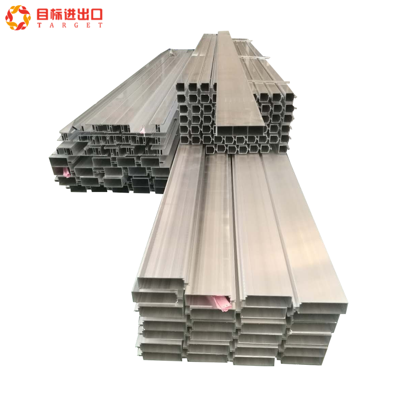
Material properties must align with your functional requirements. Over-specifying your alloy creates manufacturing bottlenecks. You must also anticipate how post-processing impacts final assembly tolerances.
Rely heavily on 6000-series alloys. These materials comprise approximately 75% of all extrusion applications globally. You should use 6063 for excellent extrudability, high thermal conductivity, and superior cosmetic finishes. If your project demands high structural integrity, step up to 6061 for higher tensile strength.
Do not select a harder alloy just to achieve strength. Hard alloys are difficult to extrude and slow down production. Instead, consider post-extrusion tempering. Applying treatments like T4, T5, or T6 helps achieve the necessary yield strength while allowing you to use a softer, easier-to-extrude base metal.
When designing an Architectural Aluminum Extrusion Profile, you must clearly designate surfaces on your engineering drawings. Mark functional surfaces as "Critical" and visible surfaces as "Cosmetic". This instructs factory workers on how to handle the parts, preventing aesthetic rejections from scratches.
You must account for dimensional growth during finishing. Anodizing adds microscopic thickness to the metal. This tiny addition can easily push tight-tolerance mating parts out of spec. Parts might slide perfectly in raw form but jam after anodizing. Furthermore, specify masking requirements early. If powder coating coats your assembly slots or internal threaded holes, you will face massive rework delays.
A brilliant design leverages the extrusion process to eliminate expensive downstream machining. By embedding smart features directly into the raw shape, you dramatically cut production steps and streamline final assembly.
You can add features to the extrusion die for free. Once the die is cut, these features replicate endlessly without adding CNC machine time.
Incorporate Index Marks: Add small, continuous V-grooves along the profile length. These act as built-in drill guides. They eliminate center-punching and expensive fixturing during CNC secondary operations.
Use Internal Webs: Thin, wide profiles tend to bow or flatten during cooling. Add internal webs to lock the dimensions in place.
Add Ribs: Flat spans often twist. Small structural ribs added to a flat surface prevent twisting and add considerable rigidity.
Avoid forcing asymmetrical or massive designs into a single, giant extrusion. Large asymmetrical profiles warp easily and require massive presses. It is often cheaper and easier to design two smaller, interlocking profiles. They extrude faster, cool straighter, and assemble quickly.
Move beyond standard friction-based T-slots for high-stress applications. Traditional T-slots loosen under vibration. Instead, design profiles that accept mechanical locking joints. Use internal threaded inserts or strong 7075-T6 connectors. This approach achieves steel-like structural rigidity without requiring any complex welding processes.
Design Method Comparison Chart | |||
Design Approach | Manufacturing Complexity | Assembly Rigidity | Best Application |
|---|---|---|---|
Monolithic (Single Huge Part) | Very High (Warping risk) | Excellent | Small volume, simple geometry |
Interlocking Profiles | Low to Medium | High (If mechanically locked) | Large complex frames |
Standard T-Slot | Low | Moderate (Vulnerable to vibration) | Light duty enclosures |
Your design is only as good as the partner executing it. You need specific criteria to select a manufacturer capable of producing complex shapes without hiding cost inflations.
Extrusion dies wear out over time. Ask your potential partner how they handle die replacements. Verify if the vendor offers tooling refunds or cost amortization for high-volume production runs. Many reputable manufacturers will waive or refund the initial die fee once you hit a specific tonnage milestone.
Do not default to 100% custom tooling immediately. Ask if the manufacturer has an existing die database. Many vendors hold thousands of standard profile elements. Utilizing an existing shape for a non-critical internal component saves you weeks of tooling time and eliminates die charges entirely.
Prioritize partners who handle extrusion, CNC machining, and finishing under one roof. When you split these services across multiple vendors, logistics become a nightmare. If a part fails final inspection, the CNC shop blames the extruder, and the extruder blames the anodizer. A single-source provider prevents this finger-pointing and takes full accountability for the tolerance stack-ups.
Effective custom aluminum extrusion design requires a careful balance between your mechanical requirements and the physical limits of extrusion. Overengineering a part by demanding zero-radius corners, unnecessary true hollows, or ultra-heavy walls creates exponential cost increases. Manufacturers will struggle to push poor designs through the press, resulting in delays, warped metal, and broken tools.
As a next-step action, review your current CAD models against the key rules established in this guide. Check your drawings against the 8-inch CCD rule, verify you have not exceeded the 3:1 tongue ratio limit, and open your screw bosses to meet the 60-degree rule. Once optimized, submit these refined drawings to your manufacturing partners for honest DFM feedback and an accurate quote.
A: Mechanical finishes, like brushing or polishing, physically alter the raw aluminum surface to create texture. Chemical finishes, like satin anodizing, alter the chemistry of the outer layer to create a protective oxide barrier. They carry vastly different costs, visual outcomes, and impacts on part tolerances. Mechanical finishes remove material, while chemical finishes generally add microscopic thickness to the part.
A: Nested hollows feature a hollow shape entirely enclosed within another hollow cavity. These require highly complex, multi-part porthole dies. Such dies are fragile, prone to failure under extreme press pressure, and struggle to maintain dimensional stability. Adding a small gap to the inner shape converts it into a manufacturable "semi-hollow," instantly solving the problem.
A: Compared to plastic injection molding, aluminum extrusion dies are relatively inexpensive. A standard die often costs between $500 and $2,000, depending heavily on the complexity and the number of cavities. Furthermore, many manufacturers happily refund the initial die cost once a specific production volume threshold is met.


