
English 
T: +86-571-8663-6649
E: hzbjys@hzbjys.com
E: hzbjys@hzbjys.com
7/F, 1st Building Of ZhongHao WangJiang International Center, NO.332 East WangJiang Road, HangZhou, ZheJiang, China.
Views: 0 Author: Site Editor Publish Time: 2026-07-22 Origin: Site


Specifying the incorrect copper thickness or alloy leads directly to catastrophic fabrication failures, compromised electrical conductivity, and unnecessary material bloat that destroys project margins. Engineers, architects, and fabricators face a fragmented measurement landscape on a daily basis. You must balance AWG gauges, ounces per square foot, mils, and decimal inches while simultaneously navigating the metallurgical differences between various copper grades. Misunderstanding these variables results in cracked bends, failed welds, and rejected parts on the shop floor. We translate project requirements into exact material specifications. This ensures the selected material meets structural, thermal, and budgetary demands without over-engineering the solution. By evaluating exact thicknesses required for different industries, you can see how material selection directly impacts shop floor workability, tooling wear, and final assembly performance.
Measurement Standardization: Copper thickness is dictated by application; roofing uses ounces (e.g., 16 oz), industrial fabrication uses AWG or inches (e.g., 0.1250”), and shielding relies on mils.
Alloy Selection is Critical: While a standard c11000 copper sheet is optimal for general electrical and architectural use, high-heat or welding applications strictly require oxygen-free copper sheet to prevent hydrogen embrittlement.
Fabrication Limits: Material thickness directly dictates the permissible bending radii, shearing tolerances, and joining methods; exceeding these limits causes cracking or structural fatigue.
Cost-to-Weight Ratio: Over-specifying thickness increases dead load and material costs exponentially; precise specification is required to balance structural integrity with budget constraints.
Buyers frequently misorder materials due to three distinct measurement systems. The copper industry uses these systems interchangeably based on the end application. This fragmentation leads to incompatible parts and severe project delays. You need a clear understanding of each standard to procure the right material. A roofing contractor speaks a different measurement language than an electrical engineer. Bridging this gap prevents costly procurement errors and ensures the shop floor receives exactly what the CAD drawing requires.
The construction and architectural sectors measure copper by weight. This system specifies how much one square foot of the material weighs in ounces. Roofing, flashing, and gutter fabrication rely entirely on this standard. It provides a quick way to calculate roof loads and structural requirements. A 16 oz copper sheet weighs exactly 16 ounces per square foot. This translates to roughly 0.0215 inches in decimal thickness. It also equals 24 gauge in the AWG system. Heavier architectural applications might require 20 oz copper. This thicker material measures approximately 0.0270 inches. Using weight simplifies bulk ordering for large surface areas. It allows architects to easily calculate the dead load added to a building structure without performing complex volumetric math.
Industrial fabrication and electrical engineering rely on the American Wire Gauge (AWG) system. They also use direct decimal inches for high-precision machining. The AWG system features an inverse relationship. A lower gauge number indicates a thicker sheet. For example, an 11 gauge sheet measures 0.1250 inches thick. A 24 gauge sheet measures only 0.0215 inches. Precision machining requires exact decimal measurements. Relying solely on gauge numbers can introduce tolerance stacking errors during assembly. Modern CNC equipment requires decimal inputs for tool path generation. Specifying 0.063 inches leaves no room for interpretation. It ensures the shop floor sets the correct shear gaps, punch clearances, and bend deductions.
Ultra-thin applications require a microscopic measurement scale. The electronics and aerospace industries use mils. One mil equals one-thousandth of an inch (0.001 inches). This standard applies to EMI shielding, RF enclosures, and printed circuit boards. Standard foil thicknesses range from 1 mil to 5 mil. A 5 mil sheet corresponds to 36 gauge. Measuring in mils provides the precision needed for delicate electronic integration. It allows engineers to calculate exact skin depth for frequency shielding. Using fractions or gauges at this scale causes dangerous rounding errors that compromise the shielding effectiveness of the final enclosure.
Procurement teams must cross-reference requirements before issuing purchase orders. Relying on verbal gauge descriptions causes expensive mistakes. We recommend implementing strict verification protocols on the shop floor.
Use physical sample kits on the shop floor to give operators a tactile reference for different gauges.
Train purchasing staff using visual thickness tutorials to bridge the gap between engineering specs and vendor catalogs.
Create an internal conversion chart tailored to your specific manufacturing niche.
Require engineers to list both the gauge and the decimal inch on all CAD drawings and flat patterns.
Force suppliers to verify the exact decimal material thickness on their order acknowledgments before shipping.
Copper Thickness Measurement Conversion Reference
Ounces (oz) | AWG Gauge | Decimal Inches | Mils | Primary Application |
|---|---|---|---|---|
- | 36 | 0.0050" | 5 | EMI Shielding / Electronics |
16 oz | 24 | 0.0215" | 21.5 | Roofing / Flashing |
20 oz | 22 | 0.0270" | 27 | Heavy Architectural |
- | 16 | 0.0508" | 50.8 | General Fabrication |
- | 11 | 0.1250" | 125 | Busbars / Structural |
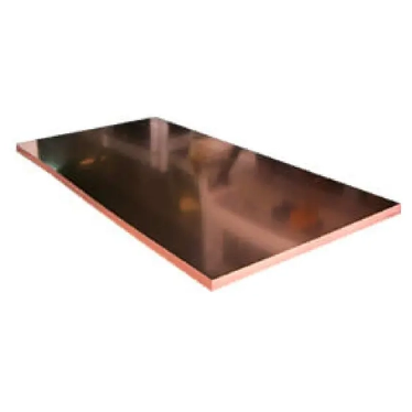
Thickness only solves half the engineering equation. You must align the metallurgical properties with the end-use environment. Differentiating between the two primary commercial copper grades prevents catastrophic field failures. The wrong alloy will crack during welding or fail under thermal stress. We categorize solutions based on purity levels and oxygen content. This dictates how the metal reacts to heat, electricity, and forming processes on the shop floor.
The industry standard for general use is Electrolytic Tough Pitch copper. A c11000 copper sheet boasts a 99.9% purity level. It delivers exceptionally high electrical and thermal conductivity. This makes it the default choice for most architectural and standard electrical projects. It forms easily on press brakes and develops a beautiful natural patina over time when exposed to the elements. However, C11000 has a severe limitation. It contains trace amounts of oxygen. When exposed to reducing gases at high temperatures, it suffers from hydrogen embrittlement. The hydrogen reacts with cuprous oxide to form steam inside the metal. This internal pressure creates micro-voids. The material becomes brittle and shatters under stress. You must never use C11000 for high-heat welding or brazing applications.
High-stress environments demand premium alternatives. Copper 101 (OFE) offers 99.99% purity. Copper 102 (OF) provides 99.95% purity. These grades contain virtually no oxygen. Specifying an oxygen-free copper sheet is non-negotiable for specific applications. High-vacuum environments require it to prevent outgassing. Sensitive electronics rely on its absolute purity for signal integrity. Most importantly, heavy welding applications demand oxygen-free grades. Without internal oxygen, hydrogen embrittlement cannot occur. The metal retains its structural integrity during TIG or MIG welding. The initial material cost is higher. However, it prevents total assembly failure during the joining process, saving thousands in scrapped parts.
Fabricators must understand the dimensional threshold separating sheets from plates. The industry defines a material as a plate when it exceeds 0.1875 inches (3/16”) in thickness. Anything thinner remains a sheet. A copper sheet plate serves entirely different engineering functions. You will find these thick plates in heavy-duty busbars. Industrial heat exchangers use them for massive thermal transfer. Structural marine components rely on plate thickness for rigidity and corrosion resistance. Machining a plate requires different tooling speeds and feeds compared to punching a thin sheet. The handling equipment must also accommodate the massive weight increase, often requiring overhead cranes or heavy-duty vacuum lifters.
Alloy Property Comparison
Alloy Grade | Purity Level | Oxygen Content | Weldability | Primary Use Case |
|---|---|---|---|---|
C11000 (ETP) | 99.90% | Trace amounts | Poor (Risk of embrittlement) | Architecture, General Electrical |
C10200 (OF) | 99.95% | Virtually None | Excellent | Standard Welding, Busbars |
C10100 (OFE) | 99.99% | None | Excellent | High-Vacuum, Advanced Electronics |
Mapping specific thicknesses to their industrial applications eliminates guesswork. Every gauge serves a distinct mechanical or electrical purpose. Engineers must match the material features to the desired project outcomes. Using a standard Copper Sheet requires evaluating the operating environment. We break down the exact specifications used across four major sectors to ensure you order the correct material for your specific fabrication needs.
Power distribution and heat dissipation require mass. Standard fabrication thicknesses for these applications range from 0.025” up to 0.125”. Switchgear components often utilize 0.040” or 0.050” material. Heavy-duty busbars require 0.063” or thicker. The cross-sectional area directly determines the ampacity. Thicker sheets carry more current without overheating. Heat sinks also rely on material thickness to draw thermal energy away from processors. You must specify high-conductivity alloys like C11000 or Copper 101. This minimizes electrical resistance. Lower resistance means less wasted energy and lower operating temperatures. Always calculate the maximum fault current before finalizing the thickness specification to prevent catastrophic melting during power surges.
Building exteriors demand a balance of weatherability and workability. The industry standard for flashing, gutters, and standing seam roofs is 16 oz (0.0216") copper. It bends easily on portable brakes at the job site. It provides excellent longevity against harsh weather. For high-wind areas or heavy snow loads, architects specify 20 oz (0.0270") sheets. The added thickness prevents oil-canning on wide flat panels. It also resists hail damage better than 16 oz material. You must evaluate the patina development timeline. Thicker sheets handle the slow oxidation process without losing structural integrity over decades. Consider the thermal expansion coefficient. Longer roof panels require thicker material to handle expansion stress without tearing at the fasteners or cleats.
Electromagnetic interference ruins sensitive electronics. Shielding requires continuous conductive barriers. We specify ultra-thin foils ranging from 0.001” to 0.005” (1 to 5 mil). A 0.001" ultra-thin copper foil sheet provides exceptional ease of handling. Fabricators can rapidly cut, punch, or shape it for complex electronic enclosures. It wraps easily around cables and internal components. Despite its thinness, it blocks high-frequency radiation effectively. Medical imaging rooms and server racks rely on these foils. The thin profile adds virtually no weight or bulk to the final product. It allows for tight integration in modern, compact device designs where space is at an absolute premium.
General sheet metal fabrication utilizes mid-range thicknesses. Deep drawing, stamping, and spinning typically require 0.032”, 0.050”, or 0.063” sheets. These gauges offer enough material to stretch without tearing. They hold complex shapes after forming. Decorative range hoods, custom sinks, and brewing equipment use these thicknesses. The material provides a rigid structure while remaining workable on standard CNC press brakes. Punching these mid-range sheets requires sharp tooling to prevent burrs. The balance between malleability and strength makes these gauges the most versatile on the shop floor. Fabricators can shear, punch, and form these sheets without requiring specialized heavy-duty machinery.
Engineering specifications often clash with shop floor realities. The physical limitations of working with different copper thicknesses dictate the manufacturing process. You must address implementation risks early in the design phase. Failing to account for workability leads to high scrap rates. It destroys tooling and causes project delays. We mitigate these risks by matching the thickness to the correct fabrication method and adjusting machine parameters accordingly.
Shearing copper requires precise machine setup. The primary risk with ultra-thin sheets is deformation. Improper shear gaps cause the material to fold or burr instead of cutting cleanly. Conversely, cutting thick plates causes excessive tool wear. Copper is gummy. It sticks to punch tooling if clearances are incorrect. We mitigate this by specifying exact tooling clearances based on decimal thickness. A standard rule is setting the die clearance to 5% of the material thickness. This ensures a clean fracture. Use sharp, polished tooling to prevent galling. Apply specialized cutting fluids to keep the tools cool and clear chips effectively during high-speed punching operations.
Thickness dictates the minimum bend radius. Forcing a tight bend on thick material causes micro-cracking along the outside radius. This compromises structural integrity. You must calculate the bend deduction accurately. Copper exhibits less springback than stainless steel, but it still requires over-bending. The temper of the copper interacts directly with the thickness. Copper 101 in H00 (cold rolled) or H01 (quarter hard) tempers behaves differently during CNC press brake forming. Standard sheet thicknesses between 0.025" and 0.063" form beautifully with an inside radius equal to one material thickness. Harder tempers require a larger radius to prevent fracturing. Always align the bend axis perpendicular to the grain direction for the best results.
Minimum Bend Radius Guidelines
Material Thickness | Soft Temper (O60) Radius | Half Hard (H02) Radius | Hard (H04) Radius |
|---|---|---|---|
0.020" - 0.032" | 0 (Sharp) | 1x Thickness | 2x Thickness |
0.040" - 0.063" | 1x Thickness | 2x Thickness | 3x Thickness |
0.125" (Plate) | 2x Thickness | 3x Thickness | 4x Thickness |
Joining copper presents unique thermal challenges. The metal conducts heat away from the weld zone rapidly. The primary risk on thin gauges (like 24 gauge) is burn-through. The arc melts away the material before a puddle forms. The risk on thick plates is inadequate heat penetration. The surrounding metal acts as a massive heat sink. We mitigate this by matching the joining method to the thickness. Use soldering or brazing for thin architectural sheets. Use TIG welding with helium shielding gas for thick plates. Helium provides a hotter arc for deep penetration. Always specify oxygen-free grades for high-heat welding. This prevents the weld pool from boiling and creating porous, weak joints. Preheating thick plates to 400°F before welding ensures proper fusion and reduces the amperage required from the welding machine.
Material capabilities must align with procurement budgets. Copper is a premium commodity. Fluctuating market prices demand strict material optimization. You must balance the required performance against the overall lifecycle cost. A framework for evaluating value prevents budget overruns. It ensures you only pay for the structural and electrical properties you actually need for the assembly to function correctly.
Efficient manufacturing starts with material yield. Standardizing sheet sizes improves nesting efficiency during CNC routing or waterjet cutting. Custom widths carry hefty mill premiums. Design your flat patterns to fit standard 36” x 96” or 48” x 120” sheets. High nesting density reduces scrap. Copper scrap holds significant recycling value, but generating it still represents lost machining time. Keep thicknesses consistent across multiple parts to minimize machine setup times. Consolidating your material orders to one or two specific gauges increases purchasing power and lowers the per-pound cost. When cutting copper on a laser, use fiber lasers rather than CO2 lasers. The reflective nature of copper damages CO2 laser optics, leading to expensive machine repairs and downtime.
Engineers often over-specify thickness as a safety factor. This practice carries exponential cost and weight penalties. Choosing a thicker gauge than structurally necessary bloats the budget immediately. It also increases the dead load. Your structural supports, fasteners, and hinges must then be upgraded to handle the extra weight. This creates a cascading cost effect. Conduct a strict trade-off analysis. Compare the upfront material cost against long-term durability. A 20 oz roof costs more initially than a 16 oz roof. However, if the building sits in a severe hail zone, the 20 oz material prevents premature replacement. Specify exactly what the environment demands, nothing more. Over-engineering a busbar by adding unnecessary thickness wastes capital that could be deployed elsewhere in the project.
Consult with a metallurgist to verify your alloy choice for extreme environments.
Request material test reports (MTRs) from your supplier to confirm exact purity levels.
Order sample cuts to verify bend radii and tooling compatibility before bulk purchasing.
Calculate the total weight impact on your structural supports before finalizing the gauge.
A: They are essentially the same thickness, measuring roughly 0.0215 inches or 21.5 mil. The difference lies in the industry standard used. Roofing and architectural trades use ounces per square foot to calculate weight loads. Industrial fabricators and machinists use the AWG gauge system to set precise tooling clearances.
A: You must specify oxygen-free grades for high-temperature welding, brazing, or high-vacuum environments. Standard C11000 contains trace oxygen. When heated, this oxygen reacts with hydrogen to form steam, causing hydrogen embrittlement. This leads to micro-cracking and total structural failure of the weld joint.
A: The industry standard threshold is 0.1875 inches. When the material exceeds 3/16 of an inch in thickness, it is classified as a plate. Plates are used for heavy structural components, massive heat exchangers, and high-capacity electrical busbars requiring extreme rigidity.
A: Ultra-thin copper foil sheets are the best choice. They typically range from 1 mil to 5 mil. This extreme thinness provides exceptional flexibility. It allows fabricators to easily cut, punch, and wrap the material around sensitive electronic enclosures without adding unnecessary weight.
A: You calculate the volume in cubic inches first. Multiply the length by the width by the decimal thickness. Then, multiply that total volume by the density of copper. The density is approximately 0.323 pounds per cubic inch. This gives you the exact weight for load calculations.


