
English 
T: +86-571-8663-6649
E: hzbjys@hzbjys.com
E: hzbjys@hzbjys.com
7/F, 1st Building Of ZhongHao WangJiang International Center, NO.332 East WangJiang Road, HangZhou, ZheJiang, China.
Views: 0 Author: Site Editor Publish Time: 2026-10-21 Origin: Site


Surface finishing dictates part longevity, environmental resilience, and functional performance. Choosing the wrong anodizing process introduces severe risks to engineering projects. You might face dimensional tolerance failures in precision machined parts. Components may suffer premature wear in harsh environments. Alternatively, you could waste budget on over-engineered finishes that offer no functional benefit. We present a data-backed evaluation framework to compare Type II (Standard) and Type III (Hardcoat) anodizing. This guide helps engineers and procurement teams align material specifications with operational requirements. It ensures strict compliance with MIL-A-8625 standards while optimizing manufacturing efficiency.
Understanding the exact technical differences between these two finishes prevents catastrophic field failures. The choice directly impacts how anodized aluminum behaves under mechanical stress, chemical exposure, and thermal cycling. We will break down the chemistry, dimensional impacts, and material compatibility of both processes. You will learn how to specify the correct finish for your exact application.
Thickness and Density: Type II produces a thinner, porous layer (0.0001”–0.0005”) ideal for dyeing, while Type III creates a dense, thick layer (typically >0.0005” up to 0.002”) engineered for extreme durability.
Dimensional Impact: Type III anodizing significantly alters part dimensions (growing outward by 50% of the total coating thickness), requiring precise pre-machining tolerance adjustments.
Performance Trade-offs: Type III offers superior abrasion and wear resistance but reduces the fatigue strength of the base aluminum and increases surface roughness; Type II offers excellent corrosion resistance and aesthetic flexibility but cannot withstand heavy mechanical wear.
Cost vs. Value: Type III requires specialized chilling equipment, higher voltage, and complex masking, making it more expensive and slower to produce than Type II, necessitating a clear ROI justification based on part application.
Engineers must define clear success criteria before specifying a surface finish. You need to identify the primary failure modes your part will encounter in the field. Parts face galvanic corrosion when mated with dissimilar metals in saltwater environments. Abrasive friction destroys raw aluminum surfaces rapidly during sliding contact. Thermal degradation compromises structural integrity in high-heat engine bays. Establish the baseline need for anodizing based on these specific operational threats. A clear understanding of the environment dictates the required oxide layer thickness and density.
Dimensional tolerance constraints play a massive role in the selection process. Pre-finish machining tolerances dictate the final geometric accuracy of precision components. You must account for coating growth during the CAD design phase. Failing to adjust pre-machining dimensions leads to parts that fail final inspection on the assembly line. Tight-tolerance bores, bearing press-fits, and fine threads are especially vulnerable to improper finish specification.
Frame the decision-making process around your primary goals using a structured approach. You must prioritize aesthetic consumer-facing branding against hidden mechanical performance.
Evaluate the mechanical load: Determine if the part experiences sliding friction, impact, or static mounting.
Assess chemical exposure: Identify if the component will face harsh solvents, saltwater, or standard atmospheric moisture.
Determine cosmetic requirements: Decide if exact color matching and high-gloss finishes are mandatory for the end user.
Calculate tolerance budgets: Review the machining drawing to see if a 2-mil coating growth will push features out of spec.
Consumer products demand vibrant colors and flawless cosmetic surfaces. Industrial machinery requires maximum hardness and wear resistance. You rarely achieve both perfectly in a single process. Acknowledge this trade-off early in the design cycle to prevent manufacturing delays.
We must clarify why MIL-A-8625 Type I is excluded from this comparison. Type I uses chromic acid to create a very thin oxide layer. Environmental regulations heavily restrict the use of hexavalent chromium globally due to toxicity. Type I remains largely confined to legacy aerospace applications and specific military repairs where fatigue life preservation is the absolute highest priority. Type II and Type III dominate modern manufacturing due to their environmental compliance, availability, and superior performance metrics.
Type II anodizing utilizes a standard sulfuric acid bath at room temperature, typically between 68°F and 72°F. The process yields a typical thickness ranging from 0.1 to 0.5 mils (0.0001" to 0.0005"). The resulting aluminum oxide layer features a highly porous hexagonal structure. This structure meets standard coating weight minimums for general corrosion protection. The room-temperature bath allows the acid to slightly dissolve the oxide as it forms. This controlled dissolution creates the characteristic microscopic pores that define Type II finishes.
This porous structure provides unmatched aesthetic flexibility. The microscopic pores easily absorb organic and inorganic dyes during the post-anodizing phase. This mechanism makes Type II the industry standard for precise color matching. It supports vibrant branding requirements for consumer goods, sporting equipment, and automotive trim. After dyeing, a sealing process using nickel acetate or hot water closes the pores. This locks in the color and prevents fading under prolonged UV exposure.
Type II excels in specific applications where aesthetics and moderate protection intersect. It works perfectly when manufacturing a decorative anodized aluminum profile for interior design or window frames. Consumer electronics enclosures benefit greatly from the flawless cosmetic finish and scratch resistance against daily handling. Architectural components use it for moderate corrosion resistance and high visual appeal. It provides a durable, cleanable surface for medical carts and laboratory equipment that face frequent chemical wipe-downs.
You must recognize the implementation risks associated with Type II. High-friction environments pose a severe threat to this finish. Abrasive forces easily breach the thin coating. This exposes the raw aluminum underneath to rapid degradation and galling. Type II cannot survive sliding wear, metal-on-metal contact, or abrasive slurry environments. It is strictly a static protective layer designed for atmospheric exposure and light handling.
Type III hardcoat requires a specialized low-temperature, high-voltage process. The sulfuric acid bath is chilled to near freezing, typically between 32°F and 40°F (0°C to 4°C). This low temperature prevents the acid from dissolving the oxide layer as it builds under high electrical current. The result is a highly dense, tightly packed oxide formation with significantly smaller pores than Type II. Standard thickness ranges from 1.0 to 2.0 mils (0.001" to 0.002"). It demands significantly higher coating weight requirements, often exceeding 4000 milligrams per square foot.
This density translates to superior wear and thermal resistance. The Type III oxide layer achieves high Vickers microhardness, often equivalent to 60-70 Rockwell C. It successfully replaces heavier metals like steel or brass in high-wear applications, saving massive amounts of weight in moving assemblies. The thick ceramic-like layer provides exceptional thermal insulation. It protects the underlying aluminum substrate from brief exposures to extreme heat, making it useful in engine components and heat shields.
Industrial and aerospace applications rely heavily on this finish for functional survival. Engineers frequently specify a hard coat aluminum extrusion for pneumatic cylinders, linear guide rails, and hydraulic actuators. Gears, valves, and sliding mechanisms demand this durable finish to prevent galling. Firearm receivers and marine hardware utilize Type III to survive punishing environments and abrasive carbon buildup. It is the ultimate functional coating for aluminum components facing mechanical abuse.
Implementation risks exist despite its extreme durability. The thick oxide layer inherently develops a dark gray, bronze, or nearly black coloration depending on the specific alloy. This severely limits dyeing options. You can typically only dye Type III black or dark green to achieve a uniform appearance. Extreme thermal cycling also introduces the risk of micro-cracking. The aluminum substrate expands faster than the rigid, ceramic oxide layer under heat. This mismatch in thermal expansion coefficients causes microscopic cracks that can compromise corrosion resistance if exposed to harsh chemicals.
We must compare Taber abrasion test expectations directly to understand the wear characteristics. Type III dominates wear resistance testing across the board. It remains mandatory for moving parts involving metal-on-metal contact. Under standard Taber testing (CS-17 wheels, 1000g load), Type III exhibits a wear index comparable to hardened steel or hard chrome plating. Type II fails rapidly under the same abrasive friction. The thin layer simply cannot support localized mechanical loads and breaks down quickly.
Evaluate salt spray test performance carefully according to ASTM B117 standards. The sealing dilemma plays a major role in corrosion resistance. Manufacturers often leave Type III unsealed. Sealing softens the hardcoat structure and reduces its peak abrasion resistance by up to 20%. A properly sealed Type II coating often provides equal or superior corrosion resistance in non-abrasive environments because the pores are completely closed. Unsealed Type III provides maximum hardness but allows harsh chemicals to eventually penetrate the micro-pores.
Surface roughness (Ra) alterations require close attention during the engineering phase. The aggressive Type III process increases the surface roughness of the machined part. A smooth 16 microinch finish may degrade to 32 microinches or worse after hardcoating. Machined parts may require post-anodize lapping, honing, or grinding. Dynamic seals, like O-rings in hydraulic cylinders, demand smooth surfaces to prevent leaks and seal wear. Type II largely maintains the pre-machined finish without degrading the Ra value significantly.
Both coatings offer excellent dielectric properties. They provide reliable electrical insulation across the surface of the aluminum part. The thicker Type III layer provides a much higher breakdown voltage, often exceeding 800 volts per mil of thickness. Electronic housings and heat sinks utilize this for superior isolation in high-voltage applications. Type II provides sufficient insulation for low-voltage consumer electronics and standard PCB standoffs.
You must address the impact on base metal fatigue strength. This is a critical engineering trade-off for aerospace and structural components. The rigid, thick Type III coating reduces the fatigue life of the underlying aluminum. Reductions can reach up to 50% in high-stress cyclic loading applications. The brittle coating initiates micro-cracks under flexing, which then propagate directly into the aluminum substrate. Type II has a negligible impact on fatigue strength due to its thin, slightly more flexible nature.
Technical Metric | Type II (Standard) | Type III (Hardcoat) |
|---|---|---|
Typical Thickness Range | 0.1 to 0.5 mils | 1.0 to 2.0 mils |
Taber Abrasion Resistance | Low to Moderate | Excellent (Comparable to steel) |
Corrosion Resistance (ASTM B117) | Excellent (When hydrothermally sealed) | Excellent (But sealing reduces peak hardness) |
Dielectric Breakdown Voltage | ~100 to 400 Volts | ~800 to 1500 Volts |
Impact on Fatigue Life | Negligible reduction | Significant reduction (Up to 50%) |
Surface Roughness (Ra) Change | Maintains original machined finish | Increases roughness significantly |
Base material influence dictates anodizing success. Alloying elements alter the density, thickness, and color of the final oxide layer. Pure aluminum (1000 series) anodizes perfectly, creating a clear, highly dense oxide. As you add alloying elements to increase mechanical strength, the anodizing process becomes more complex. The sulfuric acid bath interacts differently with copper, silicon, magnesium, and zinc.
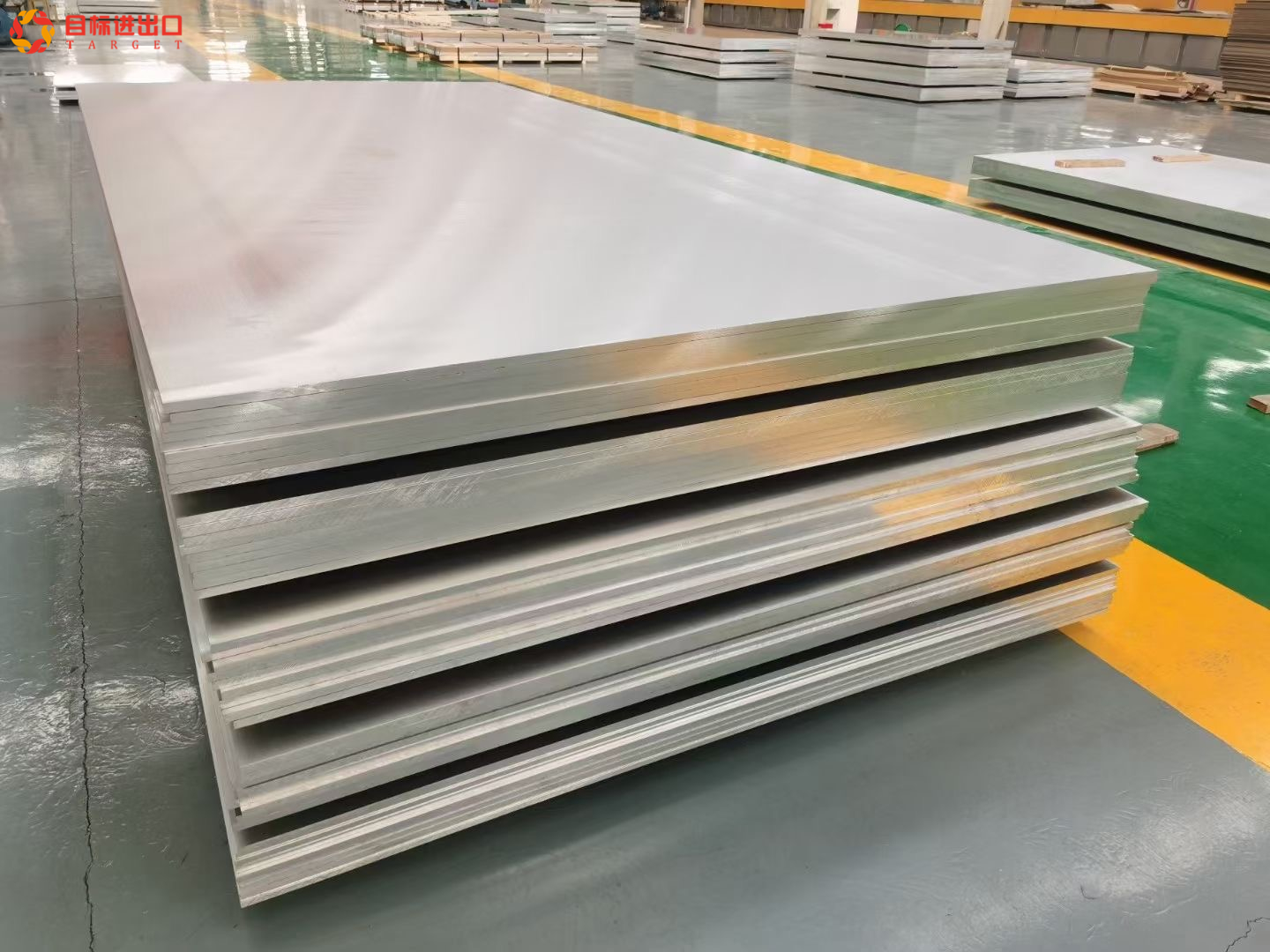
The 6000 series represents the ideal balance for manufacturing. Specifying an anodized 6061 aluminum plate is the industry gold standard. It offers an excellent combination of structural yield strength and CNC machinability. It responds exceptionally well to both Type II and Type III processes. The magnesium and silicon alloying elements do not severely disrupt the oxide formation. It yields consistent dye colors in Type II and reliable, dense hardcoat layers in Type III.
Challenges arise rapidly with 2000 and 7000 series aerospace alloys. High-copper 2000 series alloys resist thick oxide formation. The copper dissolves preferentially in the acid bath rather than oxidizing. This creates a porous, inferior hardcoat that struggles to meet MIL-SPEC thickness requirements. High-zinc 7000 series alloys pose similar challenges. They carry a high risk of burning or dissolving during the high-voltage Type III process. Operators must deploy specialized voltage step-controls and modified bath chemistries to prevent part destruction. You must consult your metal finisher before specifying hardcoat on these high-strength alloys.
Alloy Series | Primary Alloying Element | Type II Compatibility | Type III Compatibility |
|---|---|---|---|
1000 Series | None (Pure Aluminum) | Excellent (Clear, vibrant colors) | Excellent (Maximum density) |
2000 Series | Copper | Fair (Dull colors, requires care) | Poor (Resists thickness, high burn risk) |
6000 Series | Magnesium & Silicon | Excellent (Industry standard) | Excellent (Consistent hardness) |
7000 Series | Zinc | Good (Takes dark dyes well) | Fair (Requires strict voltage control) |
Managing dimensional growth requires a strict mathematical framework during the drafting phase. The 50/50 rule governs the anodizing process. Anodizing penetrates the substrate for 50% of its total thickness and builds outward for the remaining 50%. You must calculate this growth to ensure parts fit together during final assembly.
Identify the total required coating thickness (e.g., 2.0 mils for Type III).
Divide the total thickness by two to find the outward growth per surface (1.0 mil).
Multiply the outward growth by two for any diametrical features like bores or shafts (2.0 mils total diameter change).
Adjust the pre-machining CAD model to account for this exact dimensional shift.
Masking complexity drives up production labor hours. Masking critical tolerances is highly labor-intensive and requires skilled technicians. Threaded holes, electrical grounding points, and precision mating surfaces require protection from the acid bath. Type III masking is significantly more difficult. The harsh, freezing bath conditions and high agitation degrade standard masking tapes. Operators must use specialized liquid maskants, custom-molded silicone plugs, or physical hardware to seal features. This adds manual labor hours to every single batch.
Energy consumption directly impacts processing efficiency. Type III requires massive industrial chillers to maintain bath temperatures near 32°F (0°C) while fighting the heat generated by the process. It demands much higher electrical current (often 24 to 36 amps per square foot) to force the oxide layer to build against its own electrical resistance. This high energy draw makes it a more resource-intensive process compared to the room-temperature Type II process. You are paying for the electricity, the cooling capacity, and the heavy-duty titanium racking required to carry the current.
Lead times and scalability differ between the two processes. Type III requires specialized chilling equipment, high-amperage rectifiers, and robust ventilation systems. This limits vendor availability. Not every local plating shop can run true MIL-SPEC Type III hardcoat. Production lead times often extend compared to the ubiquitous Type II process. Factor this limited vendor pool into your supply chain planning and risk management strategies.
Calculate the 50/50 dimensional growth for all critical bores and adjust pre-machining tolerances directly in your CAD files.
Consult with a certified metal finishing partner during the Design for Manufacturing (DFM) phase to review alloy compatibility and racking points.
Request prototype run samples to verify surface roughness (Ra) changes before approving full-scale production runs.
Specify exact masking locations on your engineering drawings using standard color-coding or explicit callout notes.
A: Yes, but options are highly restricted. The natural thick oxide layer produces a dark gray or bronze hue depending on the alloy. This prevents vibrant color matching. You can successfully dye Type III black or very dark green, but lighter colors like red, blue, or yellow will not show up properly against the dark background.
A: Type III follows the 50/50 rule. The coating penetrates the aluminum for half its thickness and builds outward for the other half. A standard 2-mil (0.002") coating adds exactly 1 mil (0.001") of outward growth per surface. A cylindrical bore will decrease in diameter by 2 mils total.
A: Yes. The aggressive, high-voltage Type III process increases surface roughness. A smooth pre-machined finish will degrade. If your part requires a dynamic seal, you must account for this increased roughness. You may need to specify post-process lapping or grinding to restore the required finish.
A: Yes. When properly sealed, Type II provides excellent UV and weather resistance. The sealing process closes the microscopic pores, preventing moisture and corrosive agents from reaching the raw aluminum. It is the standard finish for architectural aluminum exposed to outdoor environments.
A: No. Anodizing actually highlights surface imperfections. Scratches, tool marks, and grain boundaries become more visible after the process. If you require a uniform cosmetic finish, you must apply mechanical pre-finishing techniques like bead blasting or brushing before the anodizing process.
A: Type III requires specialized industrial chillers to keep the bath near freezing and uses much higher electrical current. Additionally, masking for Type III is more labor-intensive due to the harsh bath conditions degrading standard tapes. This specialized equipment and manual labor limit vendor availability and extend production schedules.


